TwinCAT HMI project guide
TwinCAT HMI - Creating your first project*
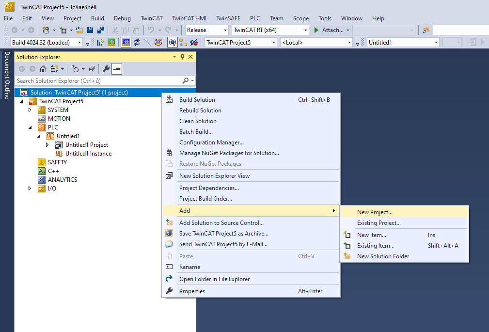
In your existing TwinCAT PLC project, add a new HMI project. In the Solution Explorer right click the Solution, than head to Add -> New Project.
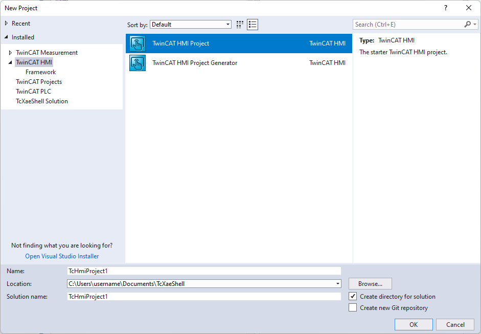
In the New Project window select the TwinCAT HMI Project option. Name your project and hit Ok!
We have just created the HMI project.
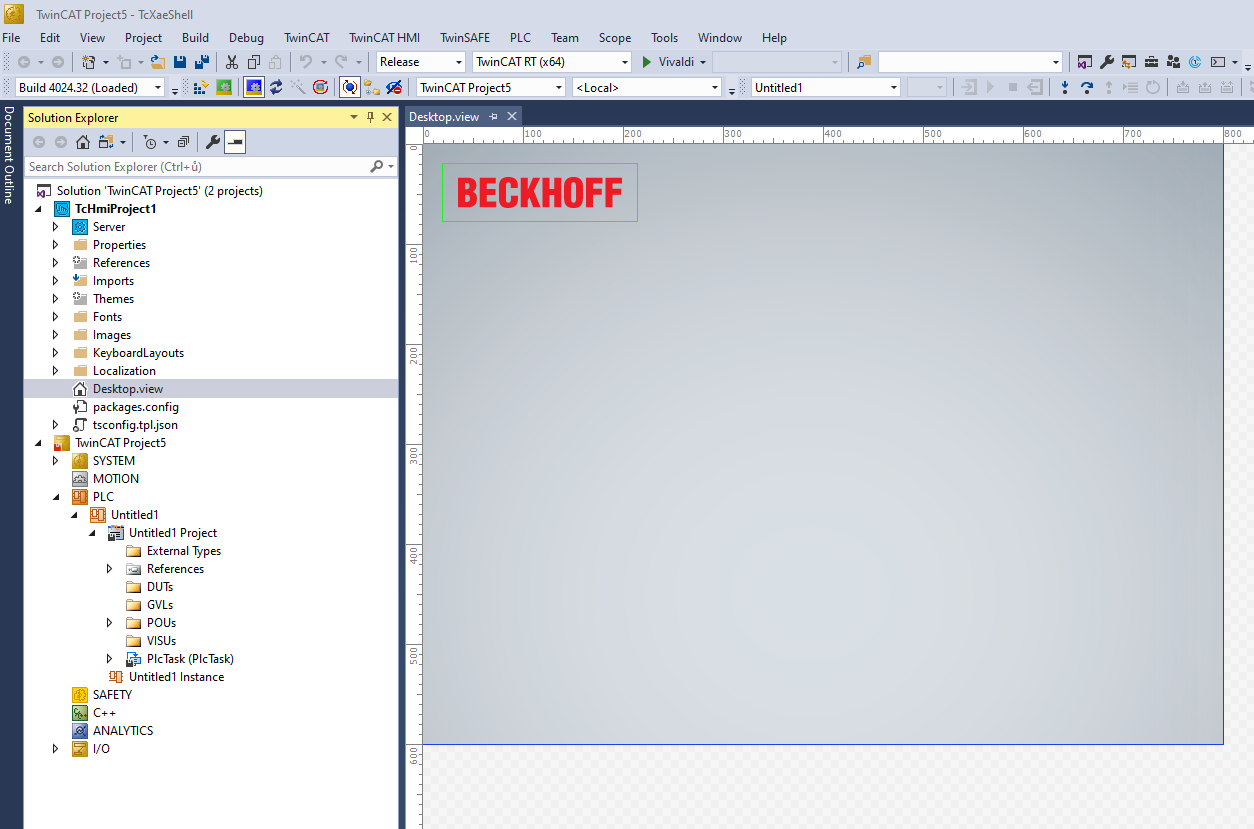
Your Solution Explorer should look similar to this. It does not matter whether the HMI project or PLC project is
first or second.
This tutorial will try just few basic functionalities so the code will be simple. You will be sufficient with only the MAIN program which you should already have. Copy these lines into your MAIN file. You can of course try implementing the HMI directly using the code already available in your PLC project. In that case, use signals that are already there to read from / write to.
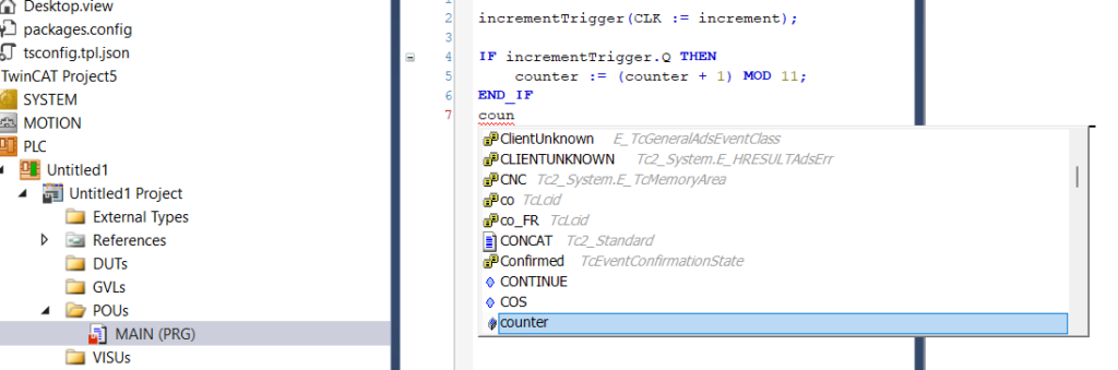
The following program checks whether increment variable was just set and if it was it adds 1 to the counter variable. The modulo operator keeps the variable in range from 0 to 10.
PROGRAM MAIN
VAR
	increment		: BOOL;
	counter			: INT;

	incrementTrigger	: R_TRIG;
END_VAR
incrementTrigger(CLK := increment);
IF incrementTrigger.Q THEN
counter := (counter + 1) MOD 11;
END_IFThen load this PLC program to your Local PLC using Activate configuration. Try to login to verify it runs in live mode. When you are done, let’s finaly get started with the HMI!
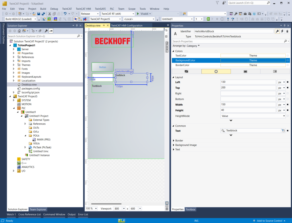
In the Solution Explorer under the HMI project open Desktop.view file as shown on the last picture. This is the default file that HMI server shows on HMI. It is similar to index.html when creating webpage.
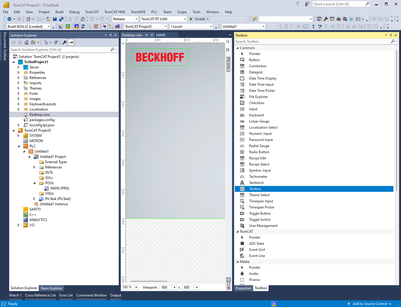
On the right side of the TwinCAT editor you should see Properties/Toolbox window. You can pin it so it stays visible because you are going to use it a lot. Feel free to also resize the window a little bit wider so you can conveniently edit Properties.
Our HMI description
We will create one button that will be binded to the increment variable. Thus when clicked will add +1 to counter variable. One input field to be able to directly change our counter variable. Then there will be two Textblocks (just simple element to display text). One of them will use an expression to add string and variable together. The other one will use event to watch for counter variable and then change color based on it’s value.
Now switch into Toolbox tab and drag and drop Button element into Desktop. Then add one Numeric Input and two Textblocks. Arrange them nicely.
Select desired element by clicking on it. You can resize it by using common controls such as dragging by the corners or move it by dragging with the mouse.
When element is selected switch right panel to Properties window. Here you will find many properties you can change.
On top of the Properties window you can find Identifier field. This is name of the element. Rename one of the Textblocks to “HelloWorldBlock” and the other one to “MessageBlock”. We made some preparation and now let’s map some variables from PLC.
Bind variable to a button
Variables (from your PLC project) can be mapped to HMI interface objects either stright using dialog window when mapping variable to element or in Configuration window (you can open it using that little C in square in that thin strip between editor window and Properties/Toolbox window). We will go the first way this time.
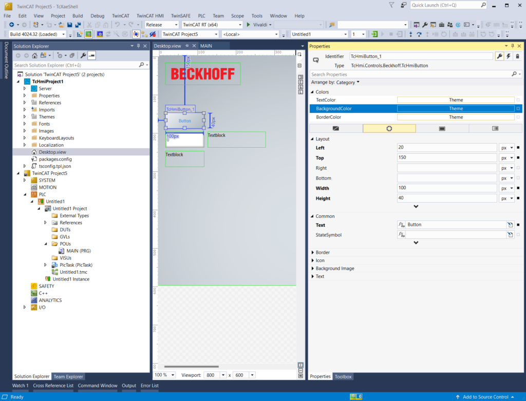
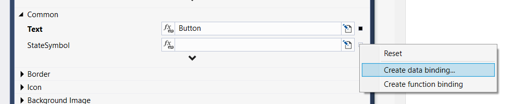
In Properties window you may have noticed like a small dots or squares on the right of the property value. This dot serves the purpose of mapping variables. Select the button element you have placed in the workspace by clicking it and head to the Properites and find StateSymbol in the Common category.
Click the dot on the right of the field and select Create data binding….
Select Server symbols tab and here navigate to the increment variable from PLC. Once you found it hit OK button in the bottom to map it. *You don’t have to click “Map Symbol” button. That is here for when you want to also map other PLC variables to the HMI before you bind this to the element. When you press OK, your selected variable is mapped automatically.
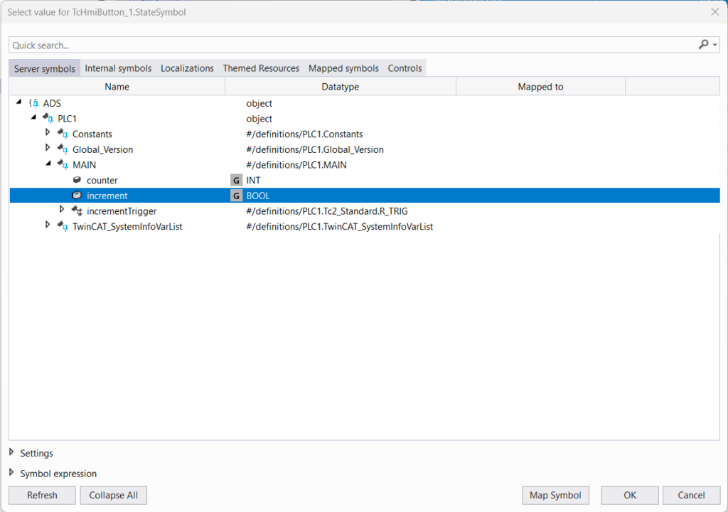
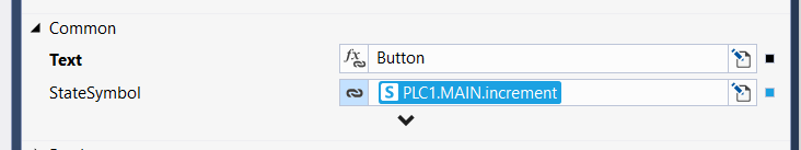
You should end up with the variable increment mapped to the StateSymbol of the button. What this is doing is that when you click the button, the mapped variable will be held TRUE as long as you hold the button. It will be reset to FALSE once you release the button. So the standard button function.
Mapping = variable from PLC is made known to the HMI (you can see all mapped variables in Configuration Window)
Binding = variable in HMI (mapped from PLC, internal or whatever) is connected to the element’s property
Bind variable to an input field
Mapping of every property is done completely same way as we did with the StateSymbol property in the button. Mapping of Value properties for input field elements is also the same but with the little twist in the end to allow write to variables.
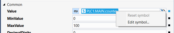
So click the Numeric Input element and find Value property in the Common category. Click the dot, select to Create data binding… and in the dialog find counter variable. This part was exactly same as with the button. Now the field can only read variable value. To make it able to write the value you have to change Binding mode.
Now you have two options. You either double click the blue symbol or right click the symbol and select Edit symbol….
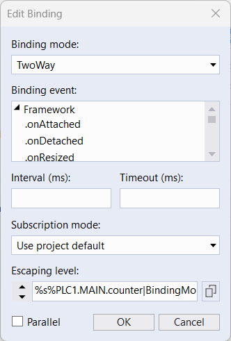
The Edit Binding dialog will show up. In the Binding mode select TwoWay option and hit OK. This ensures that element can write into variable. Remember this only applies for values of input field elements.
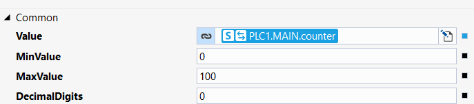
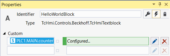
You should now end up with this binding. See the two arrows on the left of the symbol telling you it is the two way binding.
Show a message using formula
Let’s continue with another element. This time we will see how we can use the symbols to write JavaScript formulas stright into the parameter fields.
Select Textblock that we named MessageBox and find Text property in Common category. Click the dot on the right as we did before. But now select Create function binding….
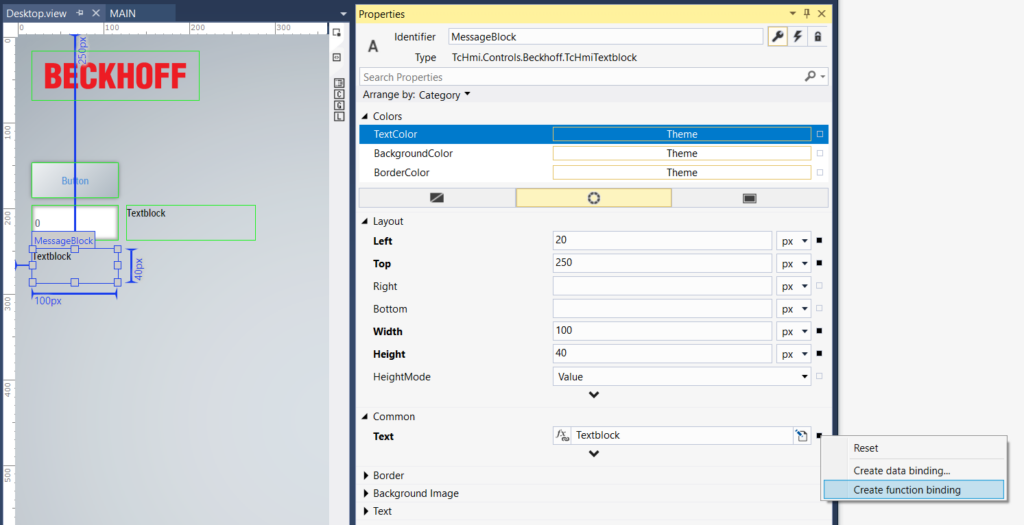
The field border will turn blue. Other way to switch between ![]() Data binding,
Data binding, ![]() Function binding or
Function binding or ![]() constant value is by clicking the symbol on the left side of the field. If you do not see any symbol here, just use the dot on the right side.
constant value is by clicking the symbol on the left side of the field. If you do not see any symbol here, just use the dot on the right side.

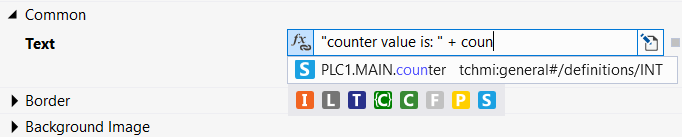
Once you have Function binding selected we can continue to add some text and values. When you are switched to the function binding, the content of the field is now JavaScript code. This brings many powerfull posibilities. When you use the binding symbols inside your JS formula, the symbols are resolved first and after that the JS code is executed. We will now write text that contains value of the counter variable.
Because we are writing JS expression you have to write string inside quotation marks. Type in the following:
"counter value is: " +
The “+” character is used to concat strings in JS. Now we want to add a symbol. If we bind the symbol using the dot on the right it will overwrite the whole field and we don’t want that. So because we have variable counter already mapped to the HMI we can start to write “counter” and TwinCAT will give you suggestions of some symbols with similar name as you write. If you for example click outside and the list of suggestions will hide you can bring it back using shortcut Ctrl + Space (the same way you bring up the code suggestions in TwinCAT PLC program editor).
Another way to do this is to Create data binding and once you have desired symbol in the field you just write the rest of the code around the symbol. Or you can copy and paste the symbols. The binding type will automatically change to the function binding.
You may have noticed Colorfull letters under the list of hints and one of the letters, the “S”, is the same as in our PLC variable symbols. These letters symbolize the symbol origin. “S” means it is server symbol (i.e. it is mapped from PLC). “I” means internal symbol (you can create variables inside HMI). “C” means controls (controls are called all elements that you place on the HMI. You can access all their parameters).
Change value using events
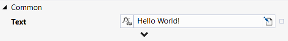
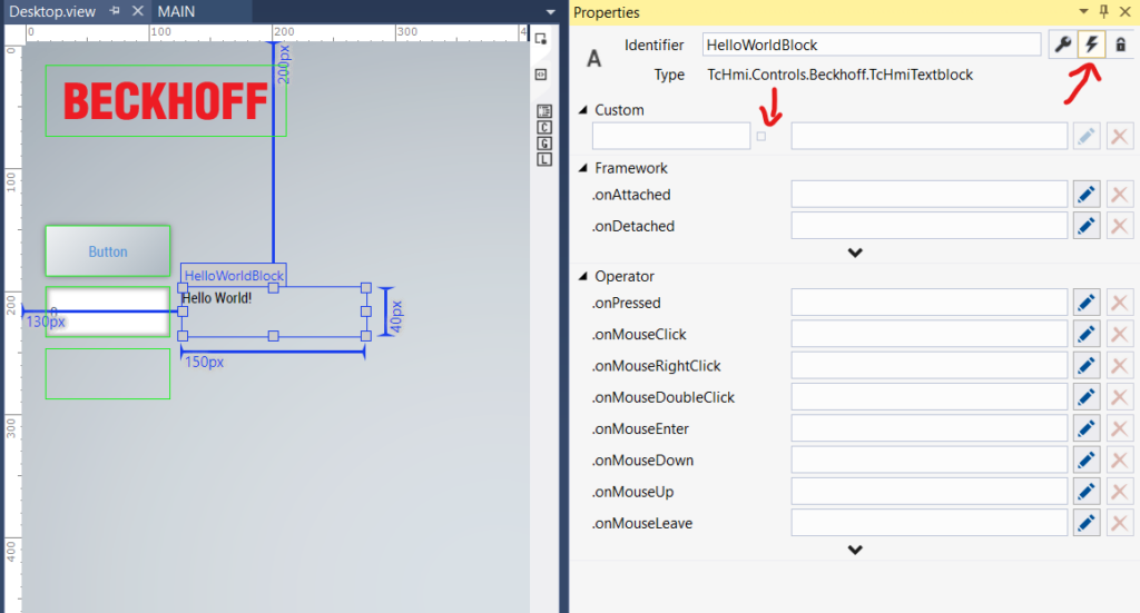
We came to our last element HelloWorldBlock. Before learning events, let’s set it’s Text property to Hello World! value and desribe logic of what we are going to do!
So our current goal is to change color of this element based on value of counter variable.
Creating events consists of three steps
- Go to Events page of Properties window
- Choose event
- Create program using graphics language
First we have to switch Properties window to Events page. That is done in Properties window in the top right corner by clicking on the icon of bolt. The key icon are properties and the lock icon are user permissions (HMI has it’s own user management and you can have different user with different permission logged in on each screen).
Here you see a list of events you can use. In Custom category you can bind variables that will be checked for value change and if the value has changed the program in the event will be executed. Then there are build-in events like .onAttached (element is attached to the webpage… = is loaded after you change the screen) or .onPressed.
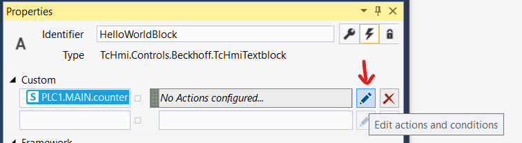
We will bind our counter variable to be watched for change. Click the dot behind empty field in Custom category. Then find our counter variable from PLC and hit Ok same as you did to bind variables before.
You should end up with event binded to counter variable. So we have our event created but it does nothing right now. Let’s add some program – some actions and conditions to it. Click the pen icon on the right.
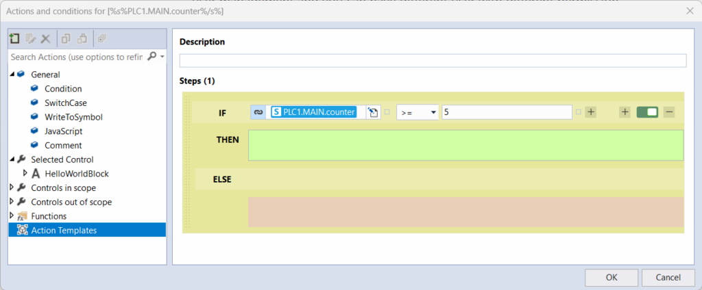
You will be greeted by an empty Actions and conditions window. Most of the window is workspace (where you build your program). On the left is the list of items you can use to create that program. In General category are building blocks of the program. Then there are 3 categories of controls. Functions are HMI wrapped JavaScript functions (there are some useful built-in functions and you can also create some yourself) and Action Templates are basically functions for this Actions and conditions graphical programing.
So let’s check the variable and do some actions. From the left column in General category drag the Condition item and drop it into the workspace. We will compare if counter variable is greater or equal to 5. Fill the fields as you learned in previous chapters.
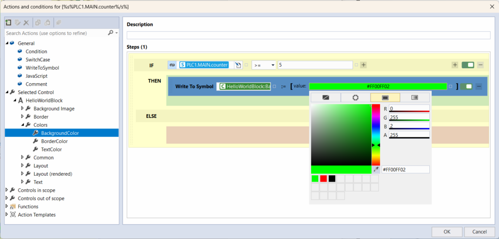
When the condition is true we will change the background color of our HelloWorldBlock to some color of your choice else we will change it back to default.
In the left column go to Selected Control category (that is our element) and find it’s BackgroundColor property. Drag that property into the green array of the THEN branch of our condition. This will automatically add WriteToSymbol action for your property. Now click the value and go to Solid color palette. Choose some nice color.
You can now select the Write To Symbol action and copy-paste it into the red area (as well as Ctrl + drag’n’drop) of the ELSE branch.
Here click the value again and change it from color palette to the Theme.
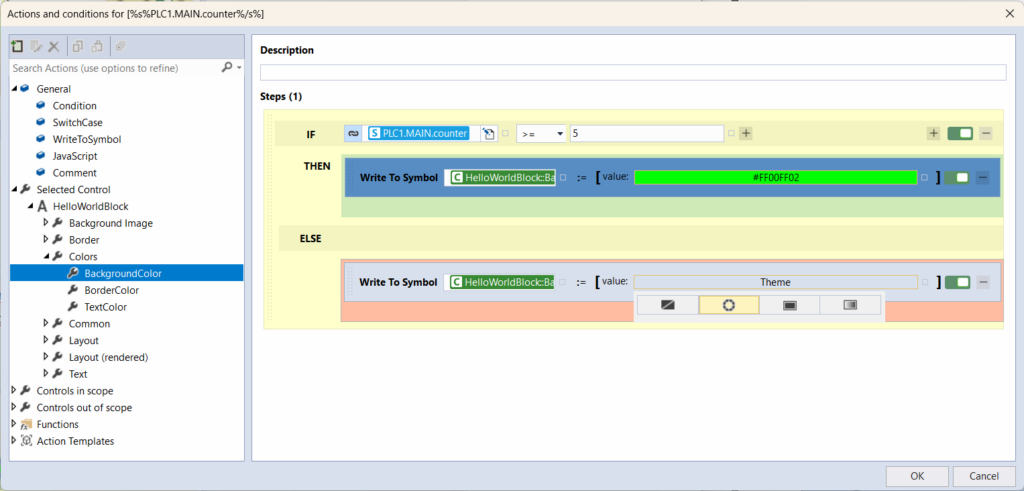
Our program for the event is done. Hit OK and you should see this. You have just created event.
Events are very usefull here. In the Custom events you can bind not just numbers or other primitive types but whole function blocks as well.
On of the most used events is .onPressed which is called after you press the button.
All elements have events. They usually have at least these basic like .onAttached and .onPressed. So you can use almost anything to serve as a button.
Show HMI in Live-View “simulation”
So we have finished our HMI and it’s time to see our result in action. For this purpose we will use something called Live-View. It is a tool for viewing your HMI without loading into PLC. What is special on this is that Live-View literaly is “Live”. You just run the Live-View in the matter of seconds and you can see all the changes you make instantly as you edit.
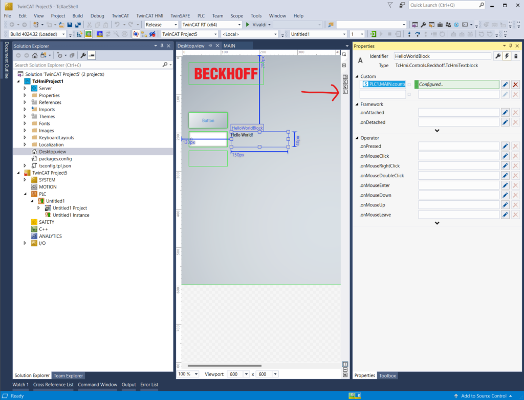
On the right edge of your workspace there is a thin strip of small and hard to click buttons. One of them is “C” for accessing HMI Configuration as I have mentioned earlier. The other one with letter “L” is for access to Live-View. The top one of these four buttons will show you Document outline window (shows a tree of elements you have placed on the screen). So let’s open Live-View by clicking on the button with “L”.
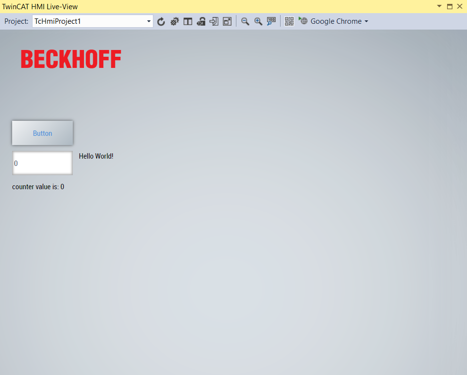
This window will show up. That’s it. You can try your HMI now.
This window is very cumbersome as you can see. You can not hide it (just close it) and it is hard to edit your HMI with this over your screen. You can also place it as a tab in TwinCAT right next to your open files. But since TwinCAT HMI editor is not exactly fast, you do not want to do that either. And there is a great other way to see Live-View.
At the end of the top toolbar in Live-View window you may recognize familiar name and it should be a name of some internet browser. By clicking on the arrow on the right you may choose which browser you want to use as default.
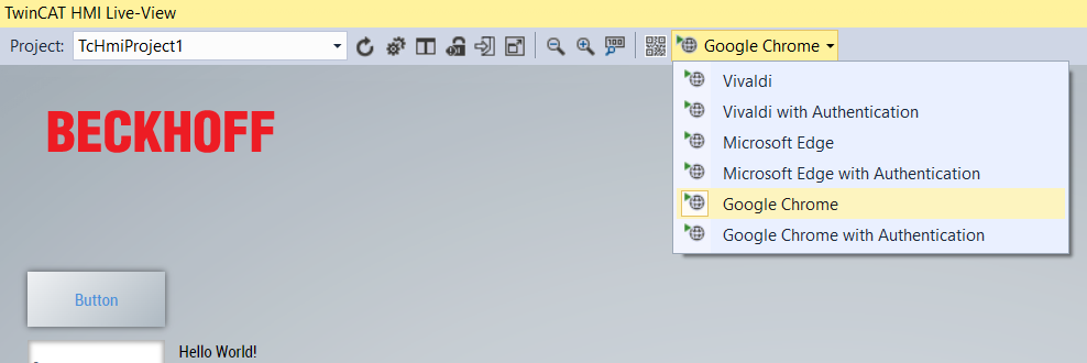
By clicking the big button with the internet browser’s name on it you will open the HMI in your internet browser.
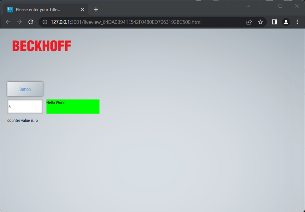
You can now fully test the HMI you created as well as you could in the Live-View window. Try to move elements around the screen to see that the update is instant.
Pressing the button will add 1 to the counter variable in PLC. You can also overwrite the variable’s value using the input field we have used. The textblock on the bottom should always show the text with the same value as in the input field. The HelloWorldBlock should change it’s color to green when the counter is 5 or more.
*this material was taken and adapted from hellotwincat.dev